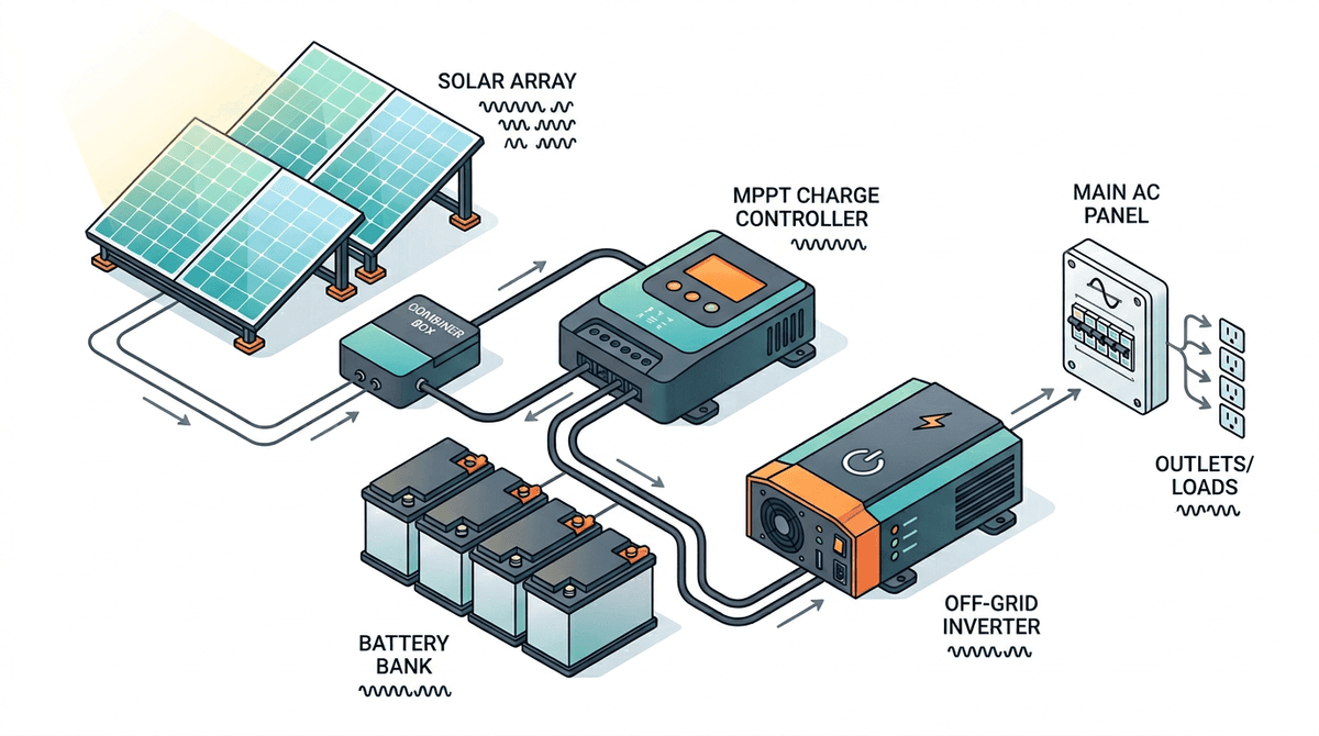
Risposta Rapida: Il cablaggio di un sistema solare off-grid segue un percorso rigoroso e sequenziale: Pannelli Solari → Scatola di Combinazione → Regolatore di Carica MPPT → Banco Batterie → Inverter → Quadro Elettrico AC. Ogni singola connessione richiede un dimensionamento specifico dei cavi in base alla corrente massima, protezione contro le sovracorrenti certificata per DC (fusibili/interruttori) per la sicurezza e un sistema di messa a terra unificato. La regola più critica del solare fai-da-te: collegare sempre il banco batterie al regolatore di carica prima di collegare i pannelli solari.
Cablare un sistema solare off-grid nell'ordine sbagliato — o con cavi sottodimensionati, fusibili mancanti o messa a terra non collegata — è la ragione più comune per cui le installazioni fai-da-te falliscono, prendono fuoco o semplicemente non funzionano in modo affidabile. Questa guida percorre il percorso completo della corrente dai pannelli solari alle prese AC, spiega ogni decisione di connessione e fornisce il dimensionamento dei cavi e le classificazioni dei fusibili per sistemi da 12 V, 24 V e 48 V.
Questa pagina è un hub: approfondisci argomenti specifici con Come Collegare i Pannelli Solari, Guida al Dimensionamento dei Cavi Solari, Fusibili e Interruttori per Sistemi Solari, Come Calcolare la Caduta di Tensione, cut-off di bassa tensione dell'inverter, Come Dimensionare un Regolatore di Carica MPPT e Dimensionamento dell'Inverter per Solare Off-Grid.
Prima di cablare qualsiasi cosa, utilizza il Calcolatore WattSizing per verificare l'uso energetico giornaliero, le ore di sole di picco e le dimensioni approssimative dei componenti. Il cablaggio segue la progettazione — ottieni prima la progettazione e le specifiche delle attrezzature dalle schede tecniche. I codici elettrici locali (ad es. NEC) e i manuali delle tue attrezzature sono autorevoli; questa guida è educativa, non un sostituto di un professionista autorizzato dove richiesto.
Prima la Tensione di Sistema: 12 V, 24 V o 48 V?
La tensione di sistema è la decisione progettuale più consequenziale. Deve essere scelta prima di acquistare qualsiasi componente.
| Tensione di Sistema | Più Adatta Per | Banco Batterie | Gamma Inverter |
|---|---|---|---|
| 12 V | Furgoni, camper, piccole cabine sotto ~1.000 W di carico | 100–300 Ah LiFePO4 | Fino a ~2.000 W |
| 24 V | Camper più grandi, piccole case, carichi 1.000–3.000 W | 200–400 Ah LiFePO4 | Fino a ~4.000 W |
| 48 V | Case off-grid, cabine, carichi sopra 3.000 W | 100–200 Ah LiFePO4 a 48 V | 3.000–10.000 W |
La fisica: Potenza (W) = Tensione (V) × Corrente (A). Alla stessa potenza, raddoppiare la tensione dimezza la corrente. Metà della corrente significa che i cavi trasportano 1/4 del calore (calore = I² × R). Un sistema da 48 V che funziona a 3.000 W assorbe 62,5 A. Un sistema da 12 V alla stessa potenza di 3.000 W assorbe 250 A — richiedendo cavi batteria classificati per 250 A, che sono costosi, pesanti, rigidi e difficili da maneggiare in sicurezza.
Regola pratica:
- Carichi sotto 1.200 W: 12 V è pratico
- Carichi 1.200–5.000 W: 24 V è efficiente
- Carichi sopra 5.000 W: 48 V è l'unica scelta ragionevole
Una volta scelto, ogni componente — batterie, regolatore di carica, inverter, barre bus DC — deve corrispondere a quella tensione.
I Componenti e i Loro Ruoli
Prima di cablare, comprendi cosa fa ogni componente e perché deve essere in sequenza.
Pannelli Solari
Convertono la luce solare in elettricità DC. Cablati in serie (per aumentare la tensione) o in parallelo (per aumentare la corrente) o entrambi. Il cablaggio in serie aumenta la tensione e consente percorsi di cavo più lunghi con cavi di calibro più piccolo. La maggior parte dei moderni regolatori di carica MPPT accetta tensioni di ingresso fino a 100–150 V DC, rendendo pratiche ed efficienti stringhe in serie di 2–4 pannelli.
Scatola di Combinazione
Unisce più stringhe di pannelli in un set di conduttori DC diretti al regolatore di carica. Include protezione contro le sovracorrenti (fusibili o interruttori) per ogni stringa. Richiesta quando più di una stringa alimenta un singolo ingresso del regolatore di carica.
Regolatore di Carica MPPT
Regola la corrente dai pannelli alle batterie. Previene il sovraccarico. Converte la tensione in eccesso dei pannelli in corrente di carica aggiuntiva — critico quando la tensione del pannello supera quella della batteria, che è la condizione normale in qualsiasi array cablato in serie correttamente progettato. Deve essere dimensionato per la potenza massima dell'array di pannelli e la tensione di ingresso massima (Voc alla temperatura minima prevista).
Banco Batterie
Immagazzina energia. Il dimensionamento determina quanti giorni di autonomia hai senza sole. La chimica LiFePO4 consente l'80–100% di profondità di scarica, funziona bene tra 0 °C e 45 °C e dura 2.000–5.000 cicli — superando di gran lunga i 400–600 cicli delle AGM.
Inverter / Inverter-Caricabatterie
Converte la DC della batteria in AC domestica (120 V o 240 V). Un inverter-caricabatterie accetta anche ingresso AC dalla rete elettrica o da un generatore e lo utilizza per ricaricare le batterie — eliminando la necessità di un caricabatterie separato. Fattore di dimensionamento critico: la potenza continua nominale deve superare il picco di carico simultaneo; la capacità di sovracorrente deve gestire l'avvio dei motori (frigoriferi, pompe per pozzi, seghe).
Quadro Elettrico AC (Sottoquadro)
Distribuisce energia AC ai circuiti con interruttori individuali, proprio come un pannello collegato alla rete. Collegato all'uscita AC dell'inverter. Il collegamento terra-neutro avviene qui in molti progetti off-grid.
Segmento 1: Pannelli Solari alla Scatola di Combinazione (o Regolatore di Carica)
Cablaggio in Serie vs. Parallelo
Cablaggio in serie (+ a − del pannello successivo): Le tensioni si sommano, la corrente rimane costante.
- 3 × pannelli da 400 W, ciascuno 40 V Vmp, 10 A Imp → Stringa: 120 V Vmp, 10 A Imp, 1.200 W
- Vantaggio: alta tensione, bassa corrente = cavo sottile, percorsi lunghi possibili
Cablaggio in parallelo (+ a +, − a −): Le correnti si sommano, la tensione rimane costante.
- 3 × pannelli da 400 W, ciascuno 40 V Vmp, 10 A Imp → Banco: 40 V Vmp, 30 A Imp, 1.200 W
- Vantaggio: un pannello ombreggiato o guasto non riduce la tensione a zero
Serie-Parallelo (più comune per array più grandi):
- Due stringhe di tre pannelli ciascuna, poi le due stringhe unite in parallelo
- Raddoppia la corrente mantenendo la tensione nel punto ottimale del regolatore di carica
Dimensionamento dei Cavi per Stringhe di Pannelli
Usa USE-2 o Cavo PV (resistente alla luce solare) all'aperto. Calcola l'amperaggio dalla corrente di cortocircuito del pannello (Isc), non dalla corrente operativa.
Amperaggio Richiesto del Conduttore = Isc del Pannello × 1,25 (fattore di sicurezza NEC)
                                     × 1,25 (fattore condotto o interramento diretto)
                                     = Isc del Pannello × 1,56
| Isc del Pannello | Amperaggio Minimo Necessario | Calibro Minimo del Cavo (USE-2, 60 °C) |
|---|---|---|
| 8 A | 12,5 A | 14 AWG |
| 10 A | 15,6 A | 14 AWG |
| 12 A | 18,8 A | 12 AWG |
| 15 A | 23,4 A | 10 AWG |
Nota: La dimensione finale del conduttore deve soddisfare amperaggio, caduta di tensione e limiti dei terminali sulla tua attrezzatura — usa la Guida al Dimensionamento dei Cavi Solari e il codice adottato nella tua giurisdizione.
Correzione della Tensione a Bassa Temperatura (Critico per la Sicurezza del Regolatore di Carica)
I pannelli al silicio producono tensione più alta con tempo freddo. La tensione di ingresso massima del regolatore di carica non deve essere superata alla temperatura più fredda che i tuoi pannelli sperimenteranno. Il fattore di correzione per i pannelli al silicio è approssimativamente 0,5% per °C sotto 25 °C.
Voc_corretto = Voc_STC × [1 + (Coeff_temp × (Temp_min − 25))]
Esempio: Tre pannelli da 400 W in serie, Voc = 49 V ciascuno, mattina più fredda = −10 °C:
Voc della stringa a STC = 3 × 49 = 147 V
Fattore di correzione temperatura = 1 + (−0,005 × (−10 − 25)) = 1 + 0,175 = 1,175
Voc_corretto = 147 × 1,175 = 173 V
Il tuo regolatore di carica deve essere classificato per almeno 173 V di ingresso — scegli un modello da 200 V per margine di sicurezza.
Fusibili per Stringhe di Pannelli
Ogni stringa ha bisogno di protezione contro le sovracorrenti all'estremità del pannello (prima della scatola di combinazione) se è presente più di una stringa. Usa solo fusibili certificati DC — i fusibili AC non possono interrompere in sicurezza la corrente di arco DC. Classificazione del fusibile = 1,56 × Isc della stringa, arrotondato per eccesso alla dimensione standard successiva del fusibile.
Segmento 2: Scatola di Combinazione al Regolatore di Carica
Questo è tipicamente un breve percorso di cavo DC di grosso calibro. Usa THWN-2 in condotto o USE-2 se interrato.
Regola di dimensionamento del cavo:
Amperaggio del Cavo = Isc Totale dell'Array × 1,25
Per un array da 1.200 W a 48 V (illustrativo — dimensiona sempre da Isc e codice, non solo da W ÷ V):
Corrente operativa dell'array ≈ 1.200 W ÷ 48 V = 25 A
Isc dell'array (supponi 10 A per stringa, due stringhe in parallelo) = 20 A
Amperaggio richiesto = 20 × 1,25 = 25 A → minimo 10 AWG
Aggiungi un interruttore DC (interruttore o interruttore con fusibile) tra il combinatore e il regolatore di carica. Questo ti consente di disattivare in sicurezza il regolatore di carica per la manutenzione senza scollegare fisicamente i connettori del pannello (che non devono mai essere scollegati sotto carico).
Segmento 3: Regolatore di Carica al Banco Batterie
Questo segmento trasporta la corrente di carica della batteria — la corrente di uscita del regolatore di carica, che può essere sostanziale.
Corrente massima di uscita = Corrente nominale del regolatore di carica (ad es., 60 A per un MPPT da 60 A)
Dimensionamento del cavo:
Amperaggio Minimo = Corrente nominale di uscita del regolatore di carica × 1,25
| Regolatore di Carica | Amperaggio Minimo | Calibro Minimo del Cavo (rame, 75 °C) |
|---|---|---|
| 20 A | 25 A | 10 AWG |
| 40 A | 50 A | 8 AWG |
| 60 A | 75 A | 6 AWG |
| 100 A | 125 A | 4 AWG |
Posizionamento del fusibile: Installa un fusibile o interruttore certificato DC sul conduttore positivo come richiesto dal codice e dal produttore — spesso il più vicino possibile al terminale della batteria. Questo protegge il cavo — non il regolatore di carica — da un cortocircuito a valle. La classificazione deve coordinarsi con l'amperaggio del cavo e le istruzioni del dispositivo.
Installazione dello shunt (opzionale ma altamente raccomandata): Uno shunt di monitoraggio della batteria (Victron BMV-712, Renogy, ecc.) va nel conduttore negativo tra il regolatore di carica e la batteria. Questo è il modo più accurato per tracciare lo stato di carica.
Segmento 4: Cablaggio del Banco Batterie
Configurazione Cella/Batteria per Tensione Desiderata
Le celle LiFePO4 hanno una tensione nominale di 3,2 V per cella. Per raggiungere la tensione di sistema:
| Tensione di Sistema | Celle in Serie | Esempio: celle da 280 Ah |
|---|---|---|
| 12 V (12,8 V nominale) | 4S | 4S = 12,8 V, 280 Ah |
| 24 V (25,6 V nominale) | 8S | 8S = 25,6 V, 280 Ah |
| 48 V (51,2 V nominale) | 16S | 16S = 51,2 V, 280 Ah |
Per aggiungere capacità (Ah), cabla banchi aggiuntivi in parallelo (+ a +, − a −). Ad esempio, due pacchi 16S da 280 Ah in parallelo = 48 V, 560 Ah = 28,7 kWh.
Regole critiche per batterie in parallelo:
- Collega solo batterie con livello di carica identico prima di parallelarle — mai collegare un banco pieno a un banco scarico
- Usa lunghezze di cavo identiche da ogni batteria parallela alle barre bus; lunghezze disallineate causano condivisione di corrente non uniforme
- Mai parallelizzare batterie di diverse capacità, età o chimiche
Cablaggio Inter-Batterie
Usa cavo di rame flessibile intrecciato con terminali ad anello. Stringi i terminali secondo le specifiche del produttore.
| Tensione di Sistema | Corrente Continua Massima | Dimensione Cavo Tipica |
|---|---|---|
| 12 V, inverter da 2.000 W | 167 A | 2/0 AWG |
| 24 V, inverter da 3.000 W | 125 A | 1/0 AWG |
| 48 V, inverter da 5.000 W | 104 A | 2 AWG |
Fusibile Classe T (Fusibile Principale Batteria)
Installa un fusibile Classe T sul cavo positivo dal banco batterie a tutti i carichi combinati. I fusibili Classe T interrompono rapidamente l'alta corrente di guasto DC e sono ampiamente utilizzati sui banchi batterie LiFePO4.
Classificazione: 125–150% della corrente di ingresso DC massima dell'inverter (conferma con il manuale dell'inverter e il codice).
Corrente di ingresso DC dell'inverter (max) = Potenza VA dell'inverter ÷ Tensione nominale della batteria
Esempio: inverter da 5.000 W a 48 V = 5.000 ÷ 48 = 104 A → Usa fusibile Classe T da 150 A
Segmento 5: Banco Batterie all'Inverter
Questo è il segmento DC a corrente più alta nell'intero sistema. Il cavo sottodimensionato qui causa caduta di tensione sotto carico, calore e possibile incendio. Il sovradimensionato è sempre sicuro.
Regola di Dimensionamento del Cavo per Cavi dell'Inverter
Corrente DC massima = Potenza continua dell'inverter ÷ Tensione nominale della batteria × 1,25
| Potenza Inverter | Tensione di Sistema | Corrente DC Massima | Cavo Raccomandato |
|---|---|---|---|
| 1.000 W | 12 V | 104 A | 1/0 AWG |
| 2.000 W | 12 V | 208 A | 4/0 AWG |
| 2.000 W | 24 V | 104 A | 1/0 AWG |
| 3.000 W | 24 V | 156 A | 3/0 AWG |
| 3.000 W | 48 V | 78 A | 4 AWG |
| 5.000 W | 48 V | 130 A | 2/0 AWG |
Mantieni questi cavi il più corti possibile — sotto 45 cm è ideale. Ogni piede extra di cavo di grosso calibro è costoso e aggiunge resistenza, causando caduta di tensione sotto carichi elevati.
Interruttori e Fusibili
Installa un interruttore o interruttore DC tra la batteria e l'inverter oltre al fusibile Classe T. Il fusibile protegge il cavo da cortocircuito catastrofico; l'interruttore consente l'isolamento sicuro per la manutenzione. Alcuni inverter hanno un interruttore DC integrato — verifica che la sua classificazione corrisponda all'amperaggio del tuo cavo.
Segmento 6: Uscita AC dell'Inverter al Quadro Elettrico AC
Questo segmento trasporta 120 V AC a corrente domestica normale. Il dimensionamento del cavo e degli interruttori segue l'Articolo 240 NEC (stesse regole della rete residenziale).
Dimensionamento del Cavo dall'Inverter al Quadro Elettrico
Corrente di uscita continua dell'inverter = VA dell'inverter ÷ 120 V
| Potenza Inverter | Corrente Uscita AC | Cavo Minimo | Interruttore nel Quadro Elettrico |
|---|---|---|---|
| 1.500 W | 12,5 A | 14 AWG | 15 A |
| 2.000 W | 16,7 A | 12 AWG | 20 A |
| 3.000 W | 25 A | 10 AWG | 30 A |
| 5.000 W | 41,7 A | 8 AWG | 50 A |
Usa THWN-2 all'interno di un condotto o Romex (NM-B) per percorsi interni protetti.
Configurazione del Quadro Elettrico
Il quadro elettrico AC per un sistema off-grid è funzionalmente identico a un sottoquadro residenziale. Differenze chiave:
- Il collegamento neutro-terra viene effettuato qui (solo in un punto — non anche all'inverter, a meno che il manuale dell'inverter non specifichi diversamente)
- Nessun interruttore principale che si collega all'utilità — il tuo "principale" è l'interruttore di uscita dell'inverter
- I circuiti individuali sono protetti con interruttori standard da 15 A o 20 A
- Un protezione contro le sovratensioni per tutta la casa dovrebbe essere installato in questo pannello
Messa a Terra: L'Unica Regola che Non Può Essere Infranta
I sistemi off-grid richiedono due sistemi di messa a terra separati ma collegati:
Conduttore di Messa a Terra dell'Attrezzatura (EGC)
Collega tutte le custodie metalliche — telai dei pannelli, telaio del regolatore di carica, telaio dell'inverter, scatola del quadro elettrico — a un punto di terra centrale. Questo trasporta la corrente di guasto in sicurezza a terra piuttosto che attraverso una persona. Tutte le messe a terra dell'attrezzatura si collegano a una barra bus di terra nel quadro elettrico AC.
Sistema di Elettrodo di Messa a Terra
La barra bus di terra si collega tramite un conduttore di rame nudo da 6 AWG (minimo) a uno o più picchetti di terra conficcati almeno 2,4 metri nel terreno presso l'edificio. Questo fornisce una tensione di riferimento relativa alla terra, protegge contro i transitori di fulmini ed è richiesto dall'NEC.
Collegamento Neutro-Terra
Effettua il collegamento neutro-terra in un solo punto: il quadro elettrico AC principale. Se lo colleghi sia all'inverter che al quadro elettrico, la corrente di terra può circolare, causando scatti anomali e potenziale pericolo di shock.
Messa a Terra del Pannello/Array Solare
Ogni telaio del pannello deve collegarsi alla messa a terra dell'attrezzatura. Se i pannelli sono su un rack metallico, collega il rack a terra. Fai passare un conduttore di messa a terra attraverso il condotto accanto ai conduttori DC fino al terminale di terra del regolatore di carica, poi alla barra bus di terra del sistema.
Fattori Cruciali di Cablaggio Spesso Trascurati
Molte guide generiche coprono le basi ma perdono le specifiche realtà fisiche che causano il sottoperformance o il guasto dei sistemi sul campo. Presta particolare attenzione a queste tre aree:
1. Caduta di Tensione su Lunghi Percorsi DC
La resistenza del cavo causa cadute di tensione sulla distanza. In una casa AC, una caduta del 3% è appena percettibile. In un sistema solare DC da 12 V o 24 V, una caduta del 3% è catastrofica. Se il tuo regolatore di carica sta inviando 14,4 V per caricare una batteria LiFePO4, ma i cavi sono troppo lunghi o troppo sottili, la batteria potrebbe vedere solo 13,8 V. Non si caricherà mai completamente.
- La Soluzione: Calcola sempre la caduta di tensione per la distanza esatta andata e ritorno dei tuoi cavi. Aumenta il calibro del cavo finché la caduta calcolata non è inferiore al 2% (idealmente inferiore all'1% per i percorsi dal regolatore di carica alla batteria).
2. Ciclo di Lavoro dell'Alternatore (Per Costruzioni di Furgoni e Camper)
Se stai costruendo un sistema off-grid mobile e prevedi di caricare le batterie domestiche dal motore del veicolo, non puoi semplicemente collegarle con cavo pesante e un relè isolatore. Gli alternatori standard dei veicoli sono progettati per ricaricare rapidamente una piccola batteria di avviamento e poi scendere a un'uscita bassa. Non sono progettati per un ciclo di lavoro continuo al 100%. Un grande banco domestico LiFePO4 assetato tirerà corrente massima continuamente, surriscaldando e distruggendo l'alternatore.
- La Soluzione: Devi usare un Caricabatterie DC-DC per limitare rigorosamente l'assorbimento di corrente a un livello sicuro (ad es., 30 A o 40 A) che l'alternatore può sostenere indefinitamente senza bruciarsi.
3. Profili di Tensione dell'Alternatore Smart
I veicoli moderni (Euro 6 e molti camion/furgoni post-2015) utilizzano "alternatori smart" che abbassano la loro tensione di uscita per risparmiare carburante una volta che la batteria di avviamento è piena. Questa tensione spesso scende sotto 13,0 V — che è del tutto insufficiente per caricare una batteria domestica LiFePO4 da 12 V.
- La Soluzione: Un relè sensibile alla tensione standard (VSR) non funzionerà. Hai bisogno di un caricabatterie DC-DC attivato dall'accensione che può aumentare la bassa tensione in ingresso fino ai 14,4 V richiesti dal tuo banco al litio.
Sequenza di Cablaggio Completa: Ordine di Costruzione Passo dopo Passo
Segui questo ordine su ogni costruzione. Energizzare i componenti fuori sequenza causa danni al regolatore di carica, cortocircuiti della batteria e guasti dell'inverter.
Passo 1 — Installa e metti a terra tutti i componenti meccanici (regolatore di carica, inverter, barre bus, quadro elettrico). Non collegare ancora nessun conduttore.
Passo 2 — Installa elettrodo di messa a terra (picchetto di terra, rame nudo alla barra bus di terra del quadro elettrico).
Passo 3 — Installa l'array di pannelli e fai passare i conduttori DC del pannello alla scatola di combinazione o al regolatore di carica. Lascia i terminali di ingresso del regolatore di carica scollegati.
Passo 4 — Cabla le celle/moduli del banco batterie alla corretta configurazione di tensione. Lascia il banco isolato — non collegare ancora a nulla.
Passo 5 — Installa portafusibile Classe T e interruttore DC tra il positivo della batteria e il bus positivo inverter/regolatore di carica. Lascia il fusibile fuori e l'interruttore aperto.
Passo 6 — Collega il regolatore di carica al banco batterie (solo terminali di uscita). I produttori di regolatori di carica richiedono il collegamento della batteria prima del collegamento del pannello.
Passo 7 — Inserisci il fusibile Classe T — il regolatore di carica è ora alimentato e visualizzerà la tensione della batteria.
Passo 8 — Collega i conduttori DC del pannello all'ingresso del regolatore di carica. Il regolatore di carica dovrebbe rilevare immediatamente la tensione del pannello e iniziare a caricare se le batterie sono sotto il setpoint.
Passo 9 — Collega i cavi DC dell'inverter al banco batterie (attraverso il fusibile/interruttore installato, che rimane aperto). Chiudi l'interruttore e verifica che l'inverter si accenda.
Passo 10 — Cabla l'uscita AC dell'inverter al quadro elettrico. Verifica il collegamento neutro-terra. Non collegare ancora i circuiti di carico.
Passo 11 — Collega i circuiti di carico AC un interruttore alla volta. Testa ogni circuito prima di aggiungere il successivo.
Passo 12 — Verifica il monitoraggio (shunt del monitor batteria, display del regolatore di carica, stato dell'inverter) mostra tensioni e correnti corrette.
Esempio Pratico Illustrativo: Sistema Cabina 48 V, 5 kW
Nota: I seguenti calcoli sono illustrativi. Usa sempre le schede tecniche delle tue attrezzature specifiche e i codici elettrici locali per il dimensionamento finale.
Carichi: 3.500 Wh/giorno domanda giornaliera totale
Posizione: Denver, CO — PSH del mese peggiore ≈ 4,6 (conferma con PVWatts o Ore di Sole di Picco per Codice Postale)
Array solare:
Dimensione array = 3.500 ÷ 0,80 efficienza ÷ 4,6 PSH = 951 W → usa 1.000 W (quattro pannelli da 250 W)
Configurazione pannello: 2 stringhe × 2 pannelli in serie = 80 V Vmp per stringa, parallele al combinatore
Banco batterie:
Giorni di autonomia: 2 giorni
Capacità batteria = 3.500 Wh × 2 ÷ 0,90 DoD (LiFePO4) = 7.778 Wh → usa 8 kWh (200 Ah a 48 V)
Configurazione: 16S celle LiFePO4 (280 Ah ciascuna) = 51,2 V, 280 Ah = 14,3 kWh (più grande del minimo → buon margine)
Regolatore di carica:
Potenza array = 1.000 W
Corrente di carica = 1.000 W ÷ 48 V = 20,8 A → usa un MPPT da 40 A (margine per futura espansione)
Tensione ingresso massima = 2 pannelli in serie × 40 V Voc = 80 V × correzione freddo (1,175) = 94 V → controller da 100 V va bene
Inverter:
Carico di picco = 2.500 W continuo, 5.000 W sovracorrente (pompa per pozzo + frigorifero + luci)
Scegli: inverter-caricabatterie da 3.000 W continuo / 6.000 W sovracorrente a 48 V
Riepilogo Dettagliato Dimensionamento Cavo e Fusibile:
| Segmento | Corrente / Calcolo | Calibro Cavo | Protezione Sovracorrente |
|---|---|---|---|
| Stringhe pannelli a combinatore | 10 A Isc × 1,56 = 15,6 A | 12 AWG USE-2 | Fusibile DC 15 A per stringa |
| Combinatore a MPPT | 20 A Isc totale × 1,25 = 25 A | 10 AWG THWN-2 | Interruttore DC 30 A |
| MPPT a batteria | 40 A uscita max × 1,25 = 50 A | 8 AWG | Interruttore DC 50 A |
| Batteria a inverter | (3000 W ÷ 48 V) × 1,25 = 78 A | 4 AWG (mantieni < 90 cm) | Fusibile Classe T 100 A |
| Uscita AC inverter a pannello | 3000 W ÷ 120 V = 25 A | 10 AWG Romex | Interruttore AC 30 A |
Errori Comuni di Cablaggio e Come Evitarli
Errore 1 — Collegare i pannelli al regolatore di carica prima della batteria La maggior parte dei controller MPPT richiede la tensione della batteria per inizializzare. Collegare prima i pannelli invia tensione non regolata ai terminali di uscita e può danneggiare permanentemente il controller. Collega sempre prima la batteria.
Errore 2 — Nessun fusibile tra batteria e inverter Un cortocircuito nei cavi dell'inverter può fornire migliaia di ampere dalla batteria in millisecondi. Senza un fusibile Classe T, il cavo diventa un elemento riscaldante. Questo è l'errore di cablaggio più pericoloso nel solare fai-da-te.
Errore 3 — Uso di fusibili certificati AC su circuiti DC I fusibili AC non possono estinguere un arco DC. La corrente DC non ha il punto di passaggio per zero che consente ai fusibili AC di interrompere. Un cortocircuito DC con un fusibile AC risulta in arco sostenuto e incendio. Usa sempre fusibili certificati DC su tutti i segmenti DC.
Errore 4 — Violazione del singolo collegamento neutro-terra Effettuare il collegamento neutro-terra sia all'inverter che al quadro elettrico crea un percorso di corrente circolante. Sintomi: scatti anomali GFCI, scatti anomali RCD/AFCI e, in alcune configurazioni, corrente elevata del cavo di terra che è un pericolo di shock.
Errore 5 — Lunghezze di cavo disallineate su stringhe di batterie in parallelo I cavi più corti hanno meno resistenza. Nelle stringhe di batterie in parallelo, la stringa con cavo più corto trasporta più corrente, invecchia più velocemente e può guastarsi mentre l'altra stringa appare sana. Usa cavi di uguale lunghezza da ogni batteria alla barra bus — questo non è opzionale.
Errore 6 — Sottodimensionamento del regolatore di carica per Voc a temperatura fredda I pannelli producono la loro tensione più alta alla temperatura più fredda. Se hai dimensionato il regolatore di carica a 25 °C STC e i tuoi pannelli raggiungono −10 °C in una mattina invernale limpida, supererai la tensione di ingresso massima del controller e lo distruggerai. Applica sempre la correzione della temperatura fredda.
Strumenti Richiesti per una Costruzione Fai-da-Te Sicura
- Multimetro digitale — verifica polarità e tensione ad ogni connessione prima di farla
- Spelacavi e crimpatore — terminali ad anello correttamente crimpati sono più sicuri e affidabili delle connessioni spellate e attorcigliate
- Chiave dinamometrica o cacciavite dinamometrico — terminali batteria serrati eccessivamente rompono i terminali della cella; terminali serrati insufficientemente producono archi
- Amperometro a pinza (compatibile DC) — verifica che la corrente operativa effettiva corrisponda ai calcoli
- Etichette per cavi e pennarello — etichetta ogni conduttore ad entrambe le estremità con la sua destinazione e polarità
Domande Frequenti
Posso usare interruttori standard AC per il mio cablaggio solare DC?
No. Gli interruttori AC si basano sulla corrente alternata che attraversa zero volt 120 volte al secondo per estinguere l'arco elettrico che si forma quando l'interruttore scatta. La corrente DC non attraversa mai zero. Se usi un interruttore AC su un circuito DC, un guasto causerà un arco sostenuto che può fondere l'interruttore e provocare un incendio. Devi usare interruttori e fusibili certificati DC.
Cosa succede se collego i miei pannelli solari al MPPT prima delle batterie?
La maggior parte dei regolatori di carica MPPT rilevano automaticamente la tensione di sistema (12V, 24V o 48V) dal banco batterie quando si avviano. Se colleghi prima i pannelli ad alta tensione, il controller non ha tensione di riferimento, non può avviarsi correttamente e la tensione non regolata del pannello può immediatamente friggere i circuiti interni del controller.
Devo mettere a terra i telai dei miei pannelli solari se sono montati su un tetto di legno?
Sì. Anche su una superficie non conduttiva come un tetto di legno, i telai metallici dei pannelli solari devono essere collegati al tuo conduttore di messa a terra dell'attrezzatura (EGC). Questo assicura che se un cavo si sfrega e tocca il telaio, la corrente di guasto abbia un percorso sicuro verso terra per far scattare l'interruttore, piuttosto che elettrificare il telaio e rappresentare un pericolo di shock.
Come cablo un caricabatterie DC-DC con un alternatore smart in un furgone?
Un alternatore smart abbassa la sua tensione di uscita per risparmiare carburante, il che significa che i relè standard sensibili alla tensione non si attiveranno. Devi cablare il caricabatterie DC-DC direttamente dalla batteria di avviamento del veicolo alla tua batteria domestica e, cosa importante, collegare il cavo "override accensione" del caricatore (spesso chiamato cavo D+) a un fusibile attivato dall'accensione nella scatola fusibili del veicolo. Questo costringe il caricatore a prelevare energia solo quando il motore è fisicamente in funzione.
Perché il mio inverter si spegne sotto carico pesante anche se la mia batteria è piena?
Questo è quasi sempre causato da caduta di tensione dovuta a cavi batteria-inverter sottodimensionati o eccessivamente lunghi. Quando si attiva un carico pesante (come un microonde), l'inverter tira corrente massiccia. Se i cavi sono troppo sottili, la resistenza causa il crollo della tensione ai terminali dell'inverter sotto la sua soglia di cutoff di bassa tensione, attivando uno spegnimento, anche se la batteria stessa è ancora completamente carica.
Ho bisogno di un elettricista per un sistema solare off-grid fai-da-te?
Dipende da dove sei e cosa colleghi. Molte giurisdizioni richiedono permessi e lavoro autorizzato per il cablaggio dei locali, anche quando il sistema non è interattivo con l'utilità. Le regole differiscono per stato, contea e AHJ. Se ti colleghi a un pannello esistente dell'edificio, vendi la proprietà o hai bisogno della firma dell'assicurazione, un elettricista autorizzato è spesso il percorso pratico. Verifica sempre i requisiti di codice e permesso locali prima di energizzare.
Fonti
- U.S. Energy Information Administration (EIA) - Electricity explained
- U.S. Department of Energy - Energy Saver
Riferimenti Fidati
- NFPA 70: National Electrical Code (NEC) — Lo standard autorevole per progettazione, installazione e ispezione elettrica sicura.
- American Boat and Yacht Council (ABYC) Standards — Linee guida essenziali per cablaggio DC, protezione contro le sovracorrenti e sicurezza in ambienti mobili e marini.
- NREL — Solar research and tools (include PVWatts e dati sulle risorse)
- Battery University — Lithium Iron Phosphate (LiFePO4)
Dimensiona Prima di Cablare
Gli errori di cablaggio più costosi derivano dalla costruzione del sistema di dimensioni sbagliate. Prima di acquistare un singolo cavo, stima i carichi giornalieri (uso energetico giornaliero per solare off-grid), scegli ore di sole di picco conservative (ore di sole di picco | Ore di Sole di Picco per Codice Postale) ed esegui il Calcolatore WattSizing per una prima distinta materiali. Quindi dimensiona conduttori e OCPD da schede tecniche + codice elettrico adottato in modo che ogni cavo trasporti ciò per cui è stato progettato.


