Wiring an off-grid solar system in the wrong order — or with undersized wire, missing fuses, or an unbonded ground — is the single most common reason DIY builds fail, catch fire, or simply never work reliably. This guide walks the complete current path from solar panels to AC outlets, explains every connection decision, and gives you the wire sizing and fuse ratings for 12 V, 24 V, and 48 V systems.
This page is a hub: deepen specific topics with series vs parallel panel wiring, solar wire sizing (AWG vs amps), fuses and breakers for solar, voltage drop on DC runs, 12V vs 24V vs 48V system voltage, MPPT sizing, and inverter sizing (continuous vs surge).
Before wiring anything, use the WattSizing Calculator to sanity-check daily energy use, peak sun hours, and rough component sizes. Wiring follows the design — get the design and equipment specs from datasheets right first. Local electrical codes (e.g. NEC) and your equipment manuals are authoritative; this guide is educational, not a substitute for a licensed professional where required.
Quick Answer: The Complete Off-Grid Signal Path
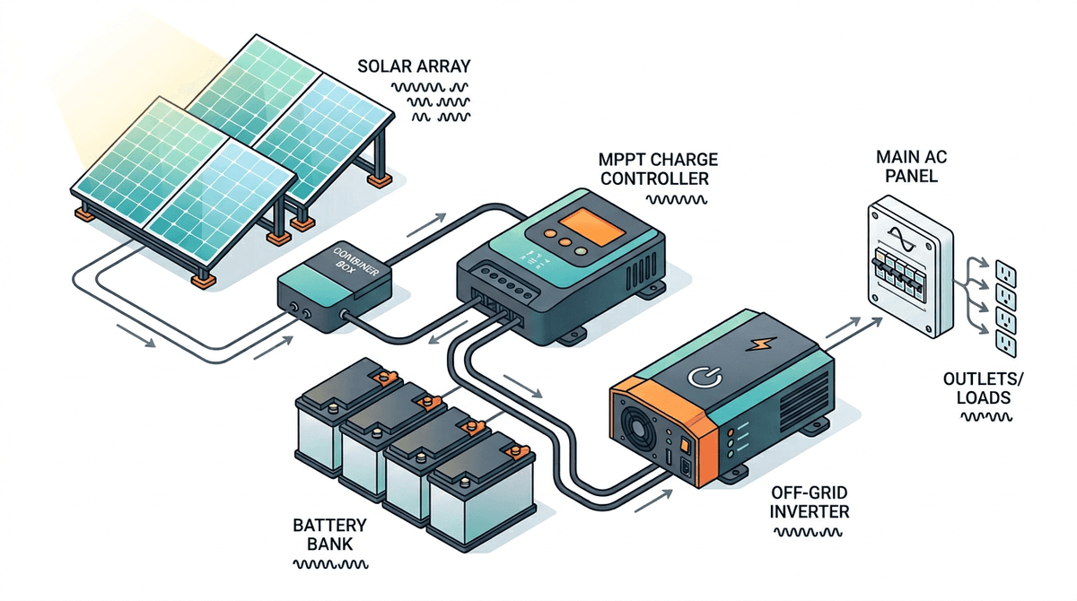
Every electron follows this path in a solar-battery-inverter system:
Solar Panels → Combiner Box → MPPT Charge Controller → Battery Bank → Inverter/Charger → AC Load Center → Loads
Each arrow is a connection that requires correct wire gauge, correct fusing, and correct polarity. We will cover every segment in order.
System Voltage First: 12 V, 24 V, or 48 V?
System voltage is the single most consequential design decision. It must be chosen before purchasing any component.
| System Voltage | Best Suited For | Battery Bank | Inverter Range |
|---|---|---|---|
| 12 V | Vans, RVs, small cabins under ~1,000 W load | 100–300 Ah LiFePO4 | Up to ~2,000 W |
| 24 V | Larger RVs, small homes, loads 1,000–3,000 W | 200–400 Ah LiFePO4 | Up to ~4,000 W |
| 48 V | Off-grid homes, cabins, loads above 3,000 W | 100–200 Ah LiFePO4 at 48 V | 3,000–10,000 W |
The physics: Power (W) = Voltage (V) × Current (A). At the same wattage, doubling voltage halves current. Half the current means wires carry 1/4 the heat (heat = I² × R). A 48 V system running 3,000 W draws 62.5 A. A 12 V system at the same 3,000 W draws 250 A — requiring battery cables rated for 250 A, which are expensive, heavy, and hard to work with safely.
Rule of thumb:
- Loads under 1,200 W: 12 V is practical
- Loads 1,200–5,000 W: 24 V is efficient
- Loads above 5,000 W: 48 V is the only reasonable choice
Once you choose, every component — batteries, charge controller, inverter, DC bus bars — must match that voltage.
The Components and Their Roles
Before wiring, understand what each component does and why it must be in sequence.
Solar Panels
Convert sunlight to DC electricity. Wired in series (to raise voltage) or parallel (to raise current) or both. Series wiring increases voltage and allows longer wire runs with smaller gauge cable. Most modern MPPT charge controllers accept input voltages up to 100–150 V DC, making series strings of 2–4 panels practical and efficient.
Combiner Box
Joins multiple panel strings into one set of DC conductors headed to the charge controller. Includes overcurrent protection (fuses or breakers) for each string. Required when more than one string feeds a single charge controller input.
MPPT Charge Controller
Regulates current from panels to batteries. Prevents overcharge. Converts excess panel voltage into additional charging current — critical when panel voltage exceeds battery voltage, which is the normal condition in any properly designed series-wired array. Must be sized for maximum panel array wattage and maximum input voltage (Voc at coldest expected temperature).
Battery Bank
Stores energy. Sizing determines how many days of autonomy you have without sun. LiFePO4 chemistry allows 80–100% depth of discharge, operates well between 32 °F and 113 °F (0–45 °C), and lasts 2,000–5,000 cycles — far exceeding AGM's 400–600 cycles.
Inverter / Inverter-Charger
Converts battery DC to household AC (120 V in the US). An inverter-charger also accepts AC input from shore power or a generator and uses it to recharge batteries — eliminating the need for a separate battery charger. Critical sizing factor: continuous wattage rating must exceed your simultaneous peak load; surge rating must handle motor-start inrush (refrigerators, well pumps, saws).
AC Load Center (Subpanel)
Distributes AC power to circuits with individual breakers, just like a grid-connected panel box. Connected to inverter AC output. Ground and neutral bonding happens here in many off-grid designs.
Generator (Optional)
Backup AC source that feeds the inverter-charger's AC input during extended cloudy periods. Properly sized generators run at 70–80% load for best fuel efficiency and longevity.
Segment 1: Solar Panels to Combiner Box (or Charge Controller)
Series vs. Parallel Wiring
Series wiring (+ to − of next panel): Voltages add, current stays constant.
- 3 × 400 W panels, each 40 V Vmp, 10 A Imp → String: 120 V Vmp, 10 A Imp, 1,200 W
- Advantage: high voltage, low current = thin wire, long runs possible
Parallel wiring (+ to +, − to −): Currents add, voltage stays constant.
- 3 × 400 W panels, each 40 V Vmp, 10 A Imp → Bank: 40 V Vmp, 30 A Imp, 1,200 W
- Advantage: one shaded or failed panel does not reduce voltage to zero
Series-Parallel (most common for larger arrays):
- Two strings of three panels each, then the two strings joined in parallel
- Doubles current while keeping voltage in the charge controller's sweet spot
Wire Sizing for Panel Strings
Use USE-2 or PV Wire (sunlight-resistant) outdoors. Calculate ampacity from the panel's short-circuit current (Isc), not the operating current.
Required Conductor Ampacity = Panel Isc × 1.25 (NEC safety factor)
                             × 1.25 (conduit or direct burial factor)
                             = Panel Isc × 1.56
| Panel Isc | Min. Ampacity Needed | Minimum Wire Gauge (USE-2, 60 °C) |
|---|---|---|
| 8 A | 12.5 A | 14 AWG |
| 10 A | 15.6 A | 14 AWG |
| 12 A | 18.8 A | 12 AWG |
| 15 A | 23.4 A | 10 AWG |
Note: Final conductor size must satisfy ampacity, voltage drop, and terminal limits on your equipment — use the AWG/amps chart and your jurisdiction's adopted code.
Cold-Temperature Voltage Correction (Critical for Charge Controller Safety)
Silicon panels produce higher voltage in cold weather. The charge controller's maximum input voltage must not be exceeded at the coldest temperature your panels will experience. The correction factor for silicon panels is approximately 0.5% per °C below 25 °C.
Voc_corrected = Voc_STC × [1 + (Temp_coeff × (Temp_min − 25))]
Example: Three 400 W panels in series, Voc = 49 V each, coldest morning = −10 °C:
String Voc at STC = 3 × 49 = 147 V
Temp correction factor = 1 + (−0.005 × (−10 − 25)) = 1 + 0.175 = 1.175
Voc_corrected = 147 × 1.175 = 173 V
Your charge controller must be rated for at least 173 V input — choose a 200 V model for safety margin.
Fusing Panel Strings
Each string needs overcurrent protection at the panel end (before the combiner box) if more than one string is present. Use DC-rated fuses only — AC fuses cannot safely interrupt DC arc current. Fuse rating = 1.56 × string Isc, rounded up to the next standard fuse size.
Segment 2: Combiner Box to Charge Controller
This is typically a short run of heavy gauge DC cable. Use THWN-2 in conduit or USE-2 if running underground.
Wire sizing rule:
Wire Ampacity = Total Array Isc × 1.25
For a 1,200 W array at 48 V (illustrative — always size from Isc and code, not from W ÷ V alone):
Array operating current ≈ 1,200 W ÷ 48 V = 25 A
Array Isc (assume 10 A per string, two strings parallel) = 20 A
Required ampacity = 20 × 1.25 = 25 A → 10 AWG minimum
Add a DC disconnect (breaker or fused disconnect) between combiner and charge controller. This allows you to safely de-energize the charge controller for maintenance without physically disconnecting panel connectors (which must never be disconnected under load).
Segment 3: Charge Controller to Battery Bank
This segment carries battery charging current — the charge controller's output current, which can be substantial.
Max output current = Charge controller rated current (e.g., 60 A for a 60 A MPPT)
Wire sizing:
Min. Ampacity = Charge controller rated output current × 1.25
| Charge Controller | Min. Ampacity | Min. Wire Gauge (copper, 75 °C) |
|---|---|---|
| 20 A | 25 A | 10 AWG |
| 40 A | 50 A | 8 AWG |
| 60 A | 75 A | 6 AWG |
| 100 A | 125 A | 4 AWG |
Fuse placement: Install a DC-rated fuse or breaker on the positive conductor as required by code and the manufacturer — often as close as practical to the battery terminal. This protects the wire — not the charge controller — from a short circuit downstream. Rating must coordinate with wire ampacity and device instructions.
Shunt installation (optional but highly recommended): A battery monitoring shunt (Victron BMV-712, Renogy, etc.) goes in the negative conductor between charge controller and battery. This is the most accurate way to track state of charge.
Segment 4: Battery Bank Wiring
Cell/Battery Configuration for Desired Voltage
LiFePO4 cells have a nominal voltage of 3.2 V per cell. To reach system voltage:
| System Voltage | Cells in Series | Example: 280 Ah cells |
|---|---|---|
| 12 V (12.8 V nominal) | 4S | 4S = 12.8 V, 280 Ah |
| 24 V (25.6 V nominal) | 8S | 8S = 25.6 V, 280 Ah |
| 48 V (51.2 V nominal) | 16S | 16S = 51.2 V, 280 Ah |
To add capacity (Ah), wire additional banks in parallel (+ to +, − to −). For example, two 16S 280 Ah packs in parallel = 48 V, 560 Ah = 28.7 kWh.
Critical parallel battery rules:
- Connect only batteries with identical charge level before paralleling — never connect a full bank to a depleted bank
- Use identical cable lengths from each parallel battery to the bus bars; mismatched lengths cause unequal current sharing
- Never parallel batteries of different capacities, ages, or chemistries
Inter-Battery Cabling
Use flexible stranded copper cable with ring terminals. Torque terminals to manufacturer spec.
| System Voltage | Max Continuous Current | Typical Cable Size |
|---|---|---|
| 12 V, 2,000 W inverter | 167 A | 2/0 AWG |
| 24 V, 3,000 W inverter | 125 A | 1/0 AWG |
| 48 V, 5,000 W inverter | 104 A | 2 AWG |
Class T Fuse (Main Battery Fuse)
Install a Class T fuse on the positive cable from the battery bank to all loads combined. Class T fuses interrupt high DC fault current quickly and are widely used on LiFePO4 battery banks.
Rating: 125–150% of the inverter's maximum DC input current (confirm with inverter manual and code).
Inverter DC input current (max) = Inverter VA rating ÷ Battery nominal voltage
Example: 5,000 W inverter at 48 V = 5,000 ÷ 48 = 104 A → Use 150 A Class T fuse
Segment 5: Battery Bank to Inverter
This is the highest-current DC segment in the entire system. Undersized cable here causes voltage drop under load, heat, and possible fire. Oversized is always safe.
Wire Sizing Rule for Inverter Cables
Max DC current = Inverter continuous watt rating ÷ Battery nominal voltage × 1.25
| Inverter Rating | System Voltage | Max DC Current | Recommended Cable |
|---|---|---|---|
| 1,000 W | 12 V | 104 A | 1/0 AWG |
| 2,000 W | 12 V | 208 A | 4/0 AWG |
| 2,000 W | 24 V | 104 A | 1/0 AWG |
| 3,000 W | 24 V | 156 A | 3/0 AWG |
| 3,000 W | 48 V | 78 A | 4 AWG |
| 5,000 W | 48 V | 130 A | 2/0 AWG |
Keep these cables as short as possible — under 18 inches (45 cm) is ideal. Each extra foot of large-gauge cable is expensive and adds resistance, causing voltage drop under high loads.
Disconnects and Fusing
Install a DC disconnect switch or breaker between battery and inverter in addition to the Class T fuse. The fuse protects the wire from catastrophic short circuit; the disconnect allows safe maintenance isolation. Some inverters have an integrated DC breaker — verify its rating matches your wire ampacity.
Segment 6: Inverter AC Output to AC Load Center
This segment carries 120 V AC at normal household current. Wire and breaker sizing follow NEC Article 240 (same rules as grid-tied residential).
Inverter to Load Center Wire Sizing
Inverter continuous output current = Inverter VA ÷ 120 V
| Inverter Rating | AC Output Current | Minimum Wire | Breaker in Load Center |
|---|---|---|---|
| 1,500 W | 12.5 A | 14 AWG | 15 A |
| 2,000 W | 16.7 A | 12 AWG | 20 A |
| 3,000 W | 25 A | 10 AWG | 30 A |
| 5,000 W | 41.7 A | 8 AWG | 50 A |
Use THWN-2 inside conduit or Romex (NM-B) for protected indoor runs.
Load Center Configuration
The AC load center for an off-grid system is functionally identical to a residential subpanel. Key differences:
- Neutral-ground bond is made here (at one point only — not also at the inverter, unless the inverter manual specifies otherwise)
- No main breaker connecting to utility — your "main" is the inverter's output breaker
- Individual circuits are protected with standard 15 A or 20 A breakers
- Whole-house surge protector should be installed at this panel
Grounding: The One Rule That Cannot Be Broken
Off-grid systems require two separate but connected grounding systems:
Equipment Grounding Conductor (EGC)
Connects all metal enclosures — panel frames, charge controller chassis, inverter chassis, load center box — to a central ground point. This carries fault current safely to ground rather than through a person.
All equipment grounds bond to a ground bus bar in the AC load center.
Grounding Electrode System
The ground bus bar connects via a 6 AWG bare copper conductor (minimum) to one or more ground rods driven at least 8 feet into the earth at the building. This provides a reference voltage relative to earth, protects against lightning transients, and is required by NEC.
Neutral-Ground Bond
Make the neutral-ground bond at one point only: the main AC load center. If you bond it at both the inverter and the load center, ground current can circulate, causing nuisance trips and potential shock hazard.
Solar Panel/Array Grounding
Each panel frame must connect to equipment ground. If panels are on a metal rack, bond the rack to ground. Run a grounding conductor through the conduit alongside the DC conductors back to the charge controller's ground terminal, then to the system ground bus.
For a dedicated walkthrough on bonding, rods, and surge paths, see grounding off-grid solar system safety.
Complete Wiring Sequence: Step-by-Step Build Order
Follow this order on every build. Energizing components out of sequence causes charge controller damage, battery short circuits, and inverter faults.
Step 1 — Install and ground all mechanical components (charge controller, inverter, bus bars, load center). Do not connect any conductors yet.
Step 2 — Install grounding electrode (ground rod, bare copper to load center ground bus).
Step 3 — Install panel array and run panel DC conductors to combiner box or charge controller. Leave charge controller input terminals disconnected.
Step 4 — Wire battery bank cells/modules to correct voltage configuration. Leave the bank isolated — do not connect to anything yet.
Step 5 — Install Class T fuse holder and DC disconnect between battery positive and inverter/charge controller positive bus. Leave fuse out and disconnect open.
Step 6 — Connect charge controller to battery bank (output terminals only). Charge controller manufacturers require battery connection before panel connection.
Step 7 — Insert Class T fuse — the charge controller is now powered and will display battery voltage.
Step 8 — Connect panel DC conductors to charge controller input. The charge controller should immediately detect panel voltage and begin charging if batteries are below setpoint.
Step 9 — Connect inverter DC cables to battery bank (through the installed fuse/disconnect, which remains open). Close the disconnect and verify the inverter powers on.
Step 10 — Wire inverter AC output to load center. Verify neutral-ground bond. Do not connect load circuits yet.
Step 11 — Connect AC load circuits one breaker at a time. Test each circuit before adding the next.
Step 12 — Verify monitoring (battery monitor shunt, charge controller display, inverter status) shows correct voltages and currents.
Worked Example: 48 V, 5 kW Cabin System
Loads: 3,500 Wh/day total daily demand
Location: Denver, CO — worst-month PSH ≈ 4.6 (confirm with PVWatts or peak sun hours by zip/state)
Solar array:
Array size = 3,500 ÷ 0.80 efficiency ÷ 4.6 PSH = 951 W → use 1,000 W (four 250 W panels)
Panel config: 2 strings × 2 panels in series = 80 V Vmp per string, paralleled at combiner
Battery bank:
Days of autonomy: 2 days
Battery capacity = 3,500 Wh × 2 ÷ 0.90 DoD (LiFePO4) = 7,778 Wh → use 8 kWh (200 Ah at 48 V)
Config: 16S LiFePO4 cells (280 Ah each) = 51.2 V, 280 Ah = 14.3 kWh (larger than minimum → good margin)
Charge controller:
Array power = 1,000 W
Charge current = 1,000 W ÷ 48 V = 20.8 A → use a 40 A MPPT (headroom for future expansion)
Max input voltage = 2 panels in series × 40 V Voc = 80 V × cold correction (1.175) = 94 V → 100 V controller is fine
Inverter:
Peak load = 2,500 W continuous, 5,000 W surge (well pump + refrigerator + lights)
Choose: 3,000 W continuous / 6,000 W surge inverter-charger at 48 V
Wire sizing summary:
| Segment | Current | Wire | Fuse |
|---|---|---|---|
| Panel strings to combiner | 10 A Isc | 12 AWG USE-2 | 15 A DC fuse per string |
| Combiner to MPPT | 20 A | 10 AWG | 30 A DC breaker |
| MPPT to battery | 40 A | 8 AWG | 50 A breaker |
| Battery to inverter | 78 A | 4 AWG | 100 A Class T |
| Inverter AC output to panel | 25 A | 10 AWG | 30 A breaker |
Common Wiring Mistakes and How to Avoid Them
Mistake 1 — Connecting panels to charge controller before battery Most MPPT controllers require battery voltage to initialize. Connecting panels first sends unregulated voltage to the output terminals and can permanently damage the controller. Always connect battery first.
Mistake 2 — No fuse between battery and inverter A short circuit in the inverter cables can deliver thousands of amps from the battery in milliseconds. Without a Class T fuse, the wire becomes a heating element. This is the most dangerous wiring mistake in DIY solar.
Mistake 3 — Using AC-rated fuses on DC circuits AC fuses cannot extinguish a DC arc. DC current does not have the zero-crossing point that allows AC fuses to interrupt. A DC short with an AC fuse results in sustained arcing and fire. Always use DC-rated fuses on all DC segments.
Mistake 4 — Single neutral-ground bond violation Making the neutral-ground bond at both the inverter and the load center creates a circulating current path. Symptoms: nuisance GFCI trips, RCD/AFCI nuisance trips, and in some configurations, elevated ground wire current that is a shock hazard.
Mistake 5 — Mismatched cable lengths on parallel battery strings Shorter cables have less resistance. In parallel battery strings, the string with shorter cable carries more current, ages faster, and can fail while the other string appears healthy. Use equal-length cables from each battery to the bus bar — this is not optional.
Mistake 6 — Undersizing the charge controller for cold-weather Voc Panels produce their highest voltage at the coldest temperature. If you sized the charge controller at 25 °C STC and your panels reach −10 °C on a clear winter morning, you will exceed the controller's maximum input voltage and destroy it. Always apply the cold-temperature correction.
Tools Required for a Safe DIY Build
- Digital multimeter — verify polarity and voltage at every connection before making it
- Wire stripper and crimper — properly crimped ring terminals are safer and more reliable than stripped-and-twisted connections
- Torque wrench or torque screwdriver — overtightened battery terminals crack cell terminals; undertightened terminals arc
- Clamp meter (DC-capable) — verify actual operating current matches calculations
- Wire labels and marker — label every conductor at both ends with its destination and polarity
FAQs
Do I need an electrician for a DIY off-grid solar system?
It depends on where you are and what you connect. Many jurisdictions require permits and licensed work for premises wiring, even when the system is not utility-interactive. Rules differ by state, county, and AHJ. If you tie into an existing building panel, sell the property, or need insurance sign-off, a licensed electrician is often the practical path. Always verify local code and permit requirements before energizing.
Can I mix panel brands in the same string?
Within a single string, all panels must be identical (same Voc, Isc, Vmp) or the weakest panel limits the entire string. Parallel strings can use different panels, but performance matching is still recommended.
What is the safest wire color convention for DC solar systems?
Red for positive, black for negative (DC), white for neutral (AC), green or bare copper for ground. Follow this consistently across the entire system to prevent mistakes during troubleshooting.
How do I protect the system from lightning?
Install a surge protection device (SPD) at the charge controller's DC input. For ground-mounted arrays, a proper grounding electrode system (ground rods bonded to panel frames and charge controller ground) provides the primary protection. Isolated ground mounts far from the building may benefit from a dedicated ground rod at the array.
My inverter has an AC input and AC output — which way does power flow?
AC input accepts generator or shore power and routes it through to loads while simultaneously charging batteries. AC output delivers inverted battery power to loads when no external AC source is present. The inverter's transfer switch (if built-in) automatically selects between sources.
Trusted References
- NEC Article 690 — Solar Photovoltaic Systems (NFPA 70)
- NREL — Solar research and tools (includes PVWatts and resource data)
- Victron Energy Wiring Unlimited — Free Technical Manual
- Battery University — Lithium Iron Phosphate (LiFePO4)
Size Before You Wire
The most expensive wiring mistakes come from building the wrong size system. Before buying a single cable, estimate daily loads (Wh/day audit), pick conservative peak sun hours (explained | by state/zip workflow), and run the WattSizing Calculator for a first-pass bill of materials. Then size conductors and OCPD from datasheets + adopted electrical code so every wire carries what it was designed for.


